News
Nov. 10, 2026
To integrate robots into an Automotive Painting System without costly rework, we recommend following a defined sequence: assess the process, confirm booth and safety requirements, select compatible robots, integrate controls, then validate coating quality before production release. This guide from Jingzhongjing Group provides actionable steps, acceptance checks, and troubleshooting advice to help your team complete the project efficiently and safely.

Automotive paint application requires repeatable gun distance, angle, speed, and overlap. Manual variation can lead to uneven film build, rework, overspray, and inconsistent appearance. A properly integrated robot can execute programmed paths consistently while reducing operator exposure to paint mist and solvents.
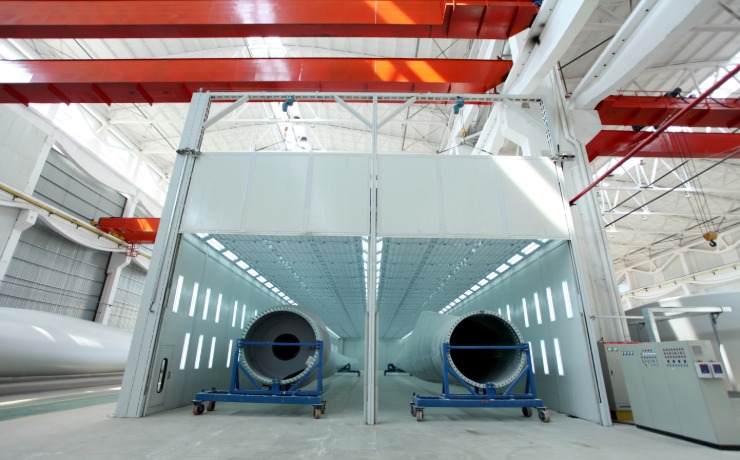
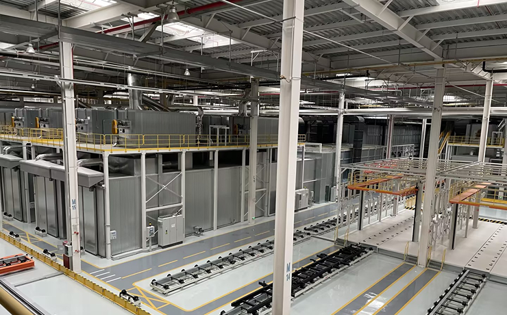
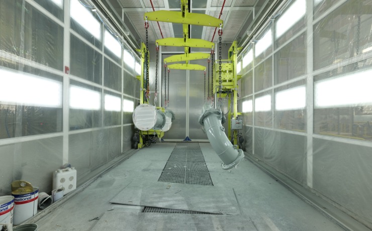
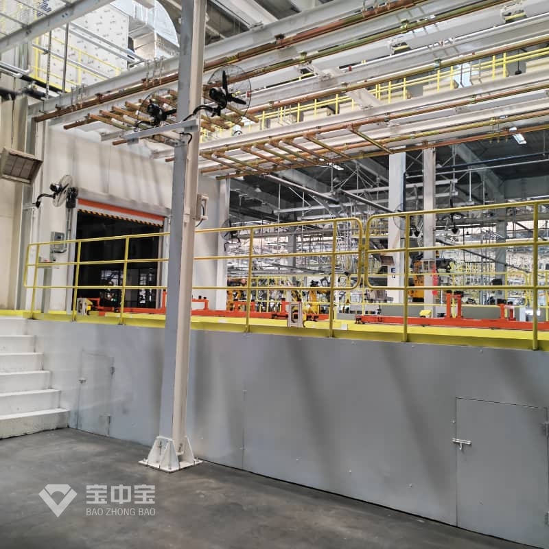
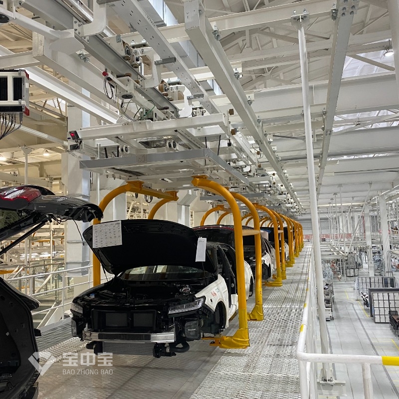
However, the robot is only one part of the process. The booth, ventilation, paint supply, atomization equipment, conveyor, safety controls, and quality inspection must work as one coordinated system. When we plan an Automotive Painting System, we treat process performance and hazardous-area safety as equally important design requirements.
Start with a process audit before specifying robot reach or payload. Record the parts and variants, takt time, conveyor speed, paint type, number of colors, target film build, and required production availability. Photograph current gun paths and note areas that are difficult to coat, such as door apertures, wheel arches, and recessed surfaces.
These baseline measurements let the project team compare the integrated cell with the existing process rather than relying on assumptions.
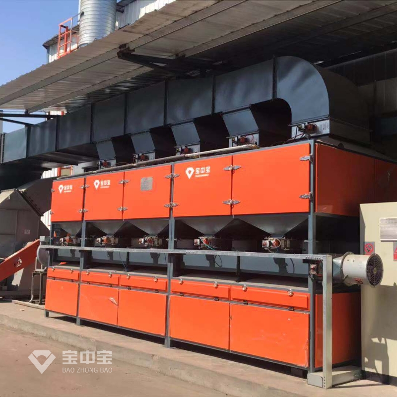
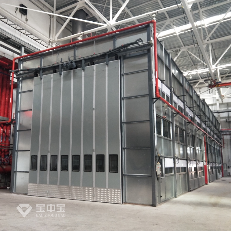
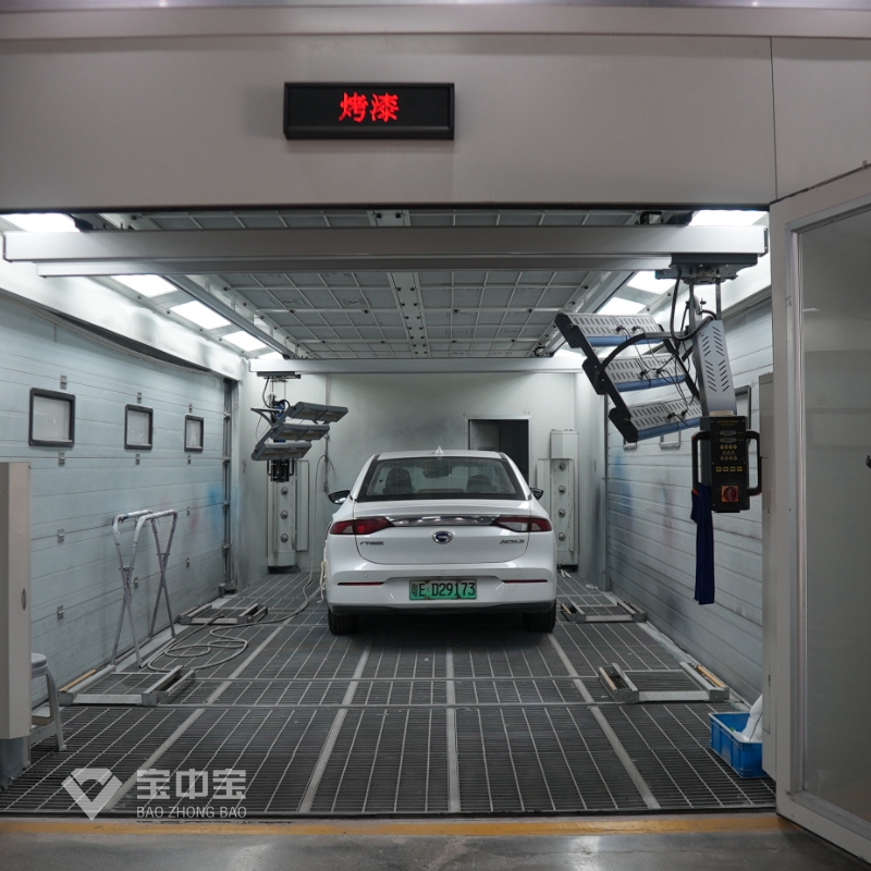
Before selecting equipment, confirm that the paint booth has the required clearance, exhaust capacity, filtration, and access for robot motion and maintenance. Review the applicable local electrical and fire codes, and specify equipment suitable for the classified hazardous location. Paint robots, applicators, hoses, grounding, and electrical components must be compatible with the facility’s zone classification and paint materials.
Use a documented risk assessment and verify safety design against applicable requirements, including ISO 10218 for industrial robot safety and ISO 13849-1 for safety-related control systems. For spray application, review the applicable edition and local adoption of NFPA 33. Standards and legal requirements vary by region; have the facility’s qualified safety and engineering professionals confirm the final design.
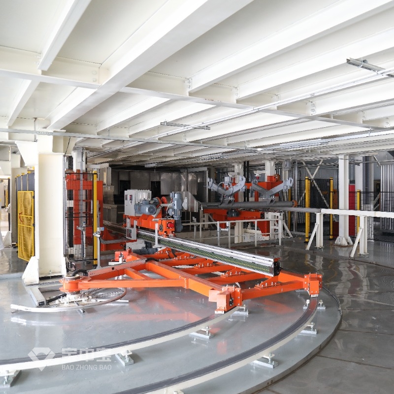
Choose the robot based on reach, payload, wrist motion, cycle time, path accuracy, environment rating, and compatibility with the coating applicator. Confirm that the robot can reach all required surfaces without singularities, collisions, or excessive hose bending. Include the paint gun or bell, color-change equipment, shaping air, fluid lines, and cable dress pack in the payload and motion review.
| Design item | What to verify |
|---|---|
| Robot envelope | Reach and wrist orientation for all part variants and programmed paths |
| Applicator | Atomization method, transfer efficiency, flow range, and coating compatibility |
| Booth interface | Airflow pattern, exhaust balance, robot access, and service clearances |
| Conveyor tracking | Encoder resolution, part position sensing, and tracking accuracy at line speed |
| Safety and utilities | Hazardous-area suitability, grounding, interlocks, air, power, and paint supply |
Do not treat a robot’s stated repeatability as the same as total coating-path accuracy. Fixture location, conveyor tracking, workpiece variation, calibration, and applicator setup all affect the final result.
Model the robot reach and collision zones against the booth, conveyor, fixtures, adjacent robots, and maintenance access. Include the complete work envelope—not just the robot base—and check both normal production and recovery positions. If the conveyor moves continuously, plan encoder-based tracking and define how the robot responds to line-speed changes or a stopped line.
Then create an interface list for the robot controller, PLC, conveyor, paint kitchen, ventilation system, and safety circuit. Define signals for part present, recipe selection, booth ready, ventilation proven, paint ready, robot fault, emergency stop, and line stop. A clear signal matrix prevents commissioning delays caused by mismatched assumptions.
Develop paths using the actual part geometry and fixture position. Set gun-to-part distance, gun angle, traverse speed, overlap, fluid flow, atomizing air, and shaping air according to the coating supplier’s technical data and validated trials. Keep path transitions smooth to avoid excess build at starts, stops, edges, and corners.
For dimensional setup, use calibrated measurement equipment appropriate to the fixture and application. A 0.01 mm instrument resolution may be useful for selected datum checks, but it is not a universal robot accuracy requirement; define tolerances from the part, fixture, and process capability needs.
Before enabling paint delivery, test the complete safety sequence. The control system should prevent spraying when required ventilation, booth status, grounding, or other defined permissives are absent. Verify emergency stops, guard or access-door interlocks, robot safe stops, conveyor stop behavior, and restart logic through documented tests.
Complete 100% functional inspection of the safety devices and interlocks in the integrated cell before production release. Record each test result, the test method, the responsible person, and any corrective action. Do not bypass an interlock to maintain production; correct the cause and repeat the verification.
Start with dry-run motion checks, then conduct controlled spray trials using representative parts and production materials. Inspect coverage, appearance, sagging, dry spray, orange peel, edge build, and film thickness. Adjust one variable at a time so the team can identify cause and effect.
Use suitable test methods for the coating and customer specification. For example, ASTM D7091 is used for nondestructive dry-film thickness measurement on metal substrates, ASTM D3359 addresses adhesion by tape testing, and ISO 2409 provides a cross-cut test method. These methods are not interchangeable acceptance limits: agree on the applicable method, sampling plan, and pass criteria with the customer and coating supplier.
Document trial results by recipe and part variant. Confirm that the process remains stable across the expected range of line speed, temperature, humidity, and material conditions before approving production.
Train operators to select recipes, recognize alarms, inspect the applicator, and follow approved recovery procedures. Train maintenance technicians on robot mastering, calibration, hose inspection, filter changes, grounding checks, and safe access to the booth. Keep the training records and maintenance tasks with the cell documentation.
Plan routine checks for atomizer condition, fluid and air leaks, booth filters, exhaust performance, conveyor tracking, fixture wear, and robot dress-pack damage. Trend defect rates and material consumption so that drift is addressed before it becomes a production issue.
For a smoother integration, we recommend assembling these resources before installation:
When evaluating Jingzhongjing Group for an Automotive Painting System project, ask for a clearly defined scope covering layout, robot interfaces, booth utilities, safety responsibilities, commissioning, training, and after-sales support. Request written response-time commitments—such as a 24-hour initial response if required by your operation—instead of assuming a service level that has not been agreed in the contract.
To put the plan into action, I recommend starting with the process audit and then working through these release gates:
Following these steps turns How to Integrate Robots into an Automotive Painting System from a broad automation question into a controlled engineering project. With process data, verified safety functions, repeatable recipes, and documented quality checks, Jingzhongjing Group and your plant team can address coating variation, operator exposure, and production efficiency with a practical, measurable integration plan.