News
Nov. 09, 2026
Planning a spray booth installation? We’ll show you how to calculate the space you need—from the booth’s internal dimensions to operator access, ductwork, and support equipment. Follow these practical steps to create a layout you can check against your building before requesting a quote from Jingzhongjing Group or committing to a Standard Spray Booth.

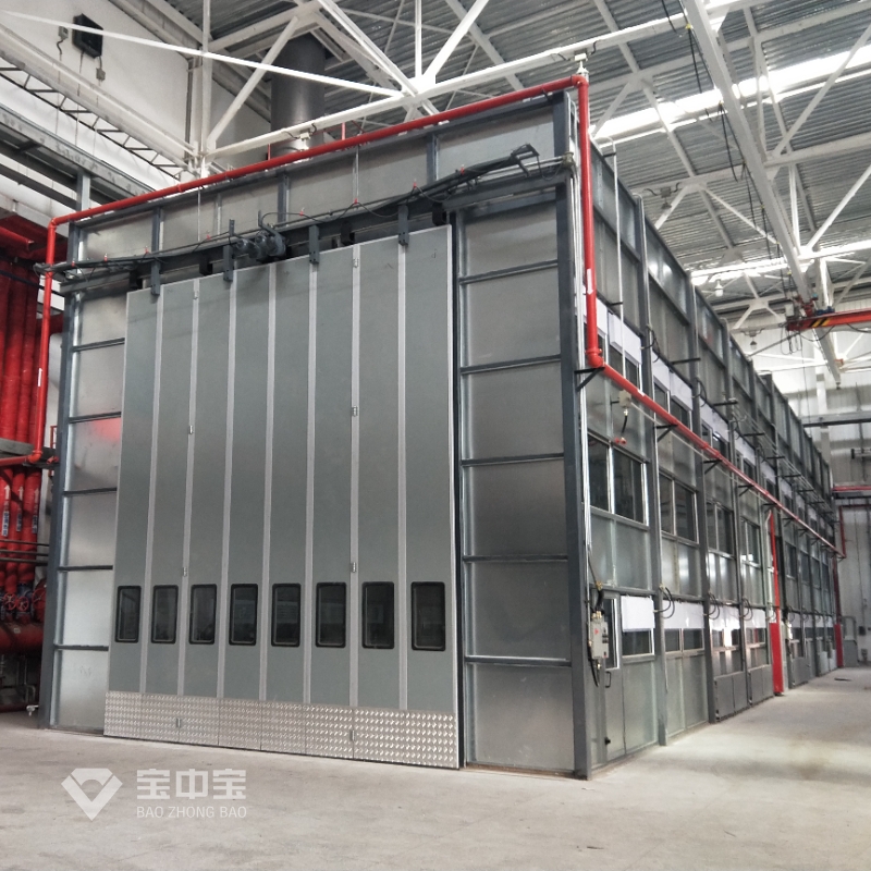
A spray booth’s advertised size may describe its working chamber, not the complete installed footprint. Before comparing models, separate the internal working dimensions from the external equipment dimensions. Then add the space required to operate, maintain, and connect the booth.
For a reliable estimate, gather these details:
Record site measurements to 0.01 m where practical, but do not mistake measurement precision for a design tolerance. Confirm final dimensions and installation tolerances with the booth supplier and qualified building and fire-safety professionals.
The simplest method is to calculate the booth, its operating envelope, and its supporting equipment as separate zones. This avoids the common mistake of ordering a booth that fits on paper but cannot be loaded or serviced in the real facility.
Measure the largest item in its actual spray orientation. Add clearance for the spray gun, operator movement, fixtures, and the airflow pattern required by the booth design. Ask the manufacturer to confirm the recommended chamber dimensions for your specific process.
As a planning example, if a component is 5.5 m long, 2.8 m wide, and 2.4 m high, a chamber with those exact internal dimensions would leave no room for handling or spraying. The final chamber must be larger; the required allowance depends on the part, application method, and booth configuration.
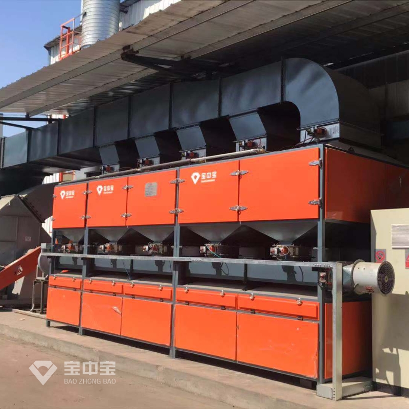
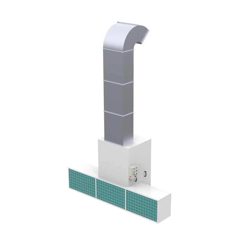
Use the manufacturer’s overall dimensions—not just the clear opening or internal chamber size. Include filter housings, fan sections, control panels, doors, and any attached plenum or equipment modules that project beyond the main enclosure.
Booth footprint (m²) = overall external length (m) × overall external width (m)
This is only the equipment footprint. It does not include operator access, maintenance clearance, ductwork, or material staging.
Mark access zones around the booth for loading, unloading, filter changes, cleaning, inspection, and emergency egress. Clearances vary by equipment design and local requirements, so treat the following numbers as an illustrative layout—not a universal code minimum:
Use the actual clearance requirements supplied by the booth manufacturer, local building and fire officials, and the applicable safety rules. A larger clearance may be needed for filter removal or heavy parts handling.
Trace the exhaust duct from the booth to its discharge point and the supply-air path back to the booth. Include elbows, transitions, fan housings, access panels, and space for inspection and cleaning. Check ceiling height and structural obstructions early; a duct route that works on a floor plan may conflict with beams, sprinklers, lighting, or other services above the booth.
Airflow is a design input, not a fixed dimension that can be guessed from booth size alone. For a simple illustration, a 4 m × 3 m open face has an area of 12 m². At a hypothetical design velocity of 0.5 m/s, the estimated airflow is 12 × 0.5 = 6 m³/s, or 21,600 m³/h. This example is not a specification: the required face velocity and exhaust volume depend on booth type, coating process, applicable requirements, and engineering design.
Also identify space and routes for compressed-air lines, electrical connections, controls, makeup-air equipment, and heating units if required. Coordinate these with the booth supplier and licensed trades before finalizing the layout.
A production-ready layout often needs more room than the booth and its access aisles. Mark separate areas for clean and coated parts, paint mixing where permitted, waste handling, carts, filters, and maintenance supplies. Keep incompatible activities and materials separated according to the coating supplier’s instructions and applicable fire and environmental requirements.
Suppose a supplier proposes a booth with external dimensions of 7.6 m long × 4.6 m wide. The booth footprint is:
7.6 × 4.6 = 34.96 m²
For an initial layout only, suppose the plan reserves 1.0 m along both sides and 1.2 m at each end for access. The resulting planning envelope is 9.6 m × 6.6 m, or 63.36 m², before adding separate duct, fan, makeup-air, staging, or utility zones.
This is a useful screening estimate, not an installation drawing. Confirm the access zones, duct arrangement, equipment projections, and required fire and building clearances for the actual model and site.
| Space item | What to measure | Why it matters |
|---|---|---|
| Working chamber | Largest part plus process-specific working allowance | Provides room to coat the part and maintain the required airflow pattern |
| External booth | Overall length and width from the equipment drawing | Defines the installed equipment footprint |
| Access envelope | Loading, door swing, operator, and maintenance zones | Prevents blocked access and difficult servicing |
| Services and ductwork | Fan, exhaust, supply air, utilities, and access panels | Helps avoid clashes with structure and other building systems |
| Support areas | Staging, carts, filters, and process-specific equipment | Supports safe and efficient production flow |
Spray finishing involves combustible materials, ventilation, electrical equipment, and exposure controls. The layout must be reviewed against the rules that apply to your location and process. In the United States, consult the applicable edition of NFPA 33, Standard for Spray Application Using Flammable or Combustible Materials, along with relevant OSHA requirements and electrical codes. Other regions may apply different national and local requirements.
Do not use a space calculation as proof of compliance. Have the proposed booth, exhaust discharge, fire protection, electrical classification, makeup air, and access arrangement reviewed by qualified professionals and the local authority having jurisdiction. Standards and requirements can change, and the correct edition depends on the project location.
We recommend starting with a measured site plan and the booth supplier’s dimensioned drawing. These tools can make the review more dependable:
Before ordering, compare the drawing with the physical site and verify 100% of the planned access and service zones during a joint review. That simple check can help prevent costly relocation, installation delays, and production interruptions.
To calculate space requirements for a Standard Spray Booth, measure the largest workpiece, confirm the booth’s external dimensions, add operating and maintenance clearances, and map the ducts, utilities, and support zones. Then review the complete plan against the actual building and applicable safety requirements.
When we plan a project with Jingzhongjing Group, we recommend sharing the workpiece dimensions, site measurements, process details, and a marked floor plan early. A dimensioned equipment proposal can then be checked against real access and service conditions before installation. Use the steps above today to identify space constraints early and move toward a practical, production-ready booth layout.